Solar
Installation (Photovoltaic)
Home
Materials
List
2 Uni-Solar 64W modules
in parallel
7.7A
operating current (full sun), 16.5V operating voltage, 23.8V open circuit
voltage, 29" x 53.8" (each panel), Anodized aluminum frame is 1.25" thick
3/16"x2"x2" aluminum
angle stock
1/4" stainless steel
bolts, lock washers and self-locking nuts
Rubber mat material
Self-leveling RV caulk
Butyl rubber caulk
1.25"x1/4 lag screws
Weather proof electrical
box
10 ga hook-up wire
6 ga cable
Connectors, silicon
dielectric grease, fuses & fuse holders
Mornigstar 15A charge
regulator.
NOTE:
All electrical connections are steel wooled then greased with silicone
dielectric grease prior to assembly. This procedure absolutely prevents
corrosion. It is well worth the extra cost and effort. I assembled
the PV charging system on my 5th wheel (7 panels, 4 golf cart batteries)
in 1999 and have not found a bit of corrosion in 10 years.
(Click on any
image to see a larger version.)
Of course, if
you're not very daring, it's best to read the instructions. I chose
to use 10 ga. stranded cable with a UV rated coating to connect the panels
in parallel and to the roof pass-through junction box and charge controller.
From the charge controller to the battery I used 6 ga stranded to minimize
the voltage drop.
(Click on any image
to see a larger version.)
Since PV cells
are less efficient when they get hot, I made stand-offs from 3/16"x2"x2"
aluminum angle stock and bolted them to the module frames with 1/4" stainless
steel bolts, lock washers and self-locking nuts. I later modified
that construction with nut inserts that attach to the frame like Pop-Rivets.
This allows me to tilt the panels up when the sun isn't directly overhead
or even remove the panels and set them on the ground. In one of the
figures below you can see the connections for the dismounted mode sticking
out in front of the battery. The extension cable is too long to fit
in the battery box.
The last picture in
this group shows me filing the sharp edges left by the cut-off saw so there
would be no chance of them cutting into the roofing material.
(Click on any image
to see a larger version.)
I made three "pigtails"
(2 for connecting the panels in parallel and one to connect to the camper
circuit) of 10 ga stranded cable and 2-terminal polarized DC connectors
which I then connected to the terminals in the junction boxes on the under
side of the panels. When all connections were made, I attached the
lid and sealed all joints & holes with caulk. The last picture
in the group shows a 2"x2"x 48" aluminum angle support rib hot glued and
caulked to the back side of the panel. We get a pretty heavy snow
load in Michigan and I wanted to remove some of the stress by supporting
the middle of the panel.
(Click on any image
to see a larger version.)
Roof installation
started with pieces of rubber truck bed mat to make up the gap between
the support rib and the roof and to prevent wear on the roof. I set
the panels in place, drew extended lines around the stand-offs and drilled
pilot holes in the roof through the pre-drilled stand-off holes.
I had to take a chance on drilling/screwing through an electrical cable
because Lance wouldn't answer my request for diagrams. I
deposited a big gob of Dicor Self-Leveling Lap Sealant each stand-off location
then set the panels back in place. Being extra cautious to avoid
stripping the wood by over tightening, I used 1.25"x1/4 lag screws to fasten
the standoffs to the roof. A little experimenting with a light duty
torque wrench and a piece of 3/8" plywood gave me a pretty good idea of
how much torque could be applied before the wood stripped out. As
you can see by the last picture in the group, there isn't much room left
at the front of the camper roof.
(Click on any image
to see a larger version.)
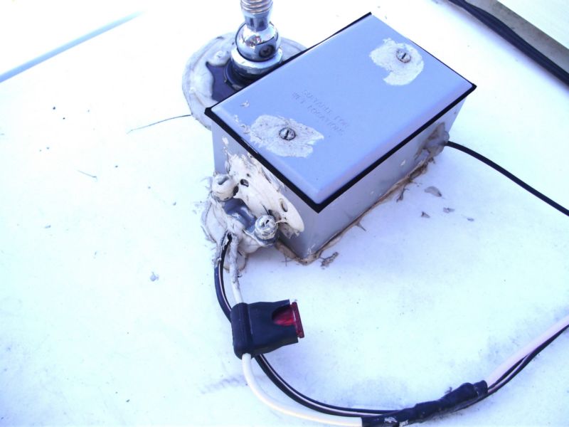
In the first picture
in this group you can see the plug/socket/fuse connection that connects
the panels in parallel. The cables are taped to the roof with white
duct tape to keep the wind from whipping the cables around. As I
do when I want to protect my ham radio antenna connections, I taped the
connectors with electrical tape and then coated the tape with caulk provide
a better moisture seal and to keep the tape from deteriorating. The
middle picture shows the weather proof electrical box which I glued to
the roof with caulk then securely screwed to the roof through screw holes
in the bottom of the box. I then drilled a half-inch hole through
the roof and into the end of an overhead cupboard where Lance designers
located a "wiring closet". Of course, before I drilled, I did a bit
of investigation and measuring to make sure the hole would end up where
I wanted it. The last picture in the group above shows the charge
regulator installed on the outside of the "wiring closet".
(Click on any image
to see a larger version.)
On the left in
the group above is a close up of the Morningstar 15 amp controller.
I have the 25 amp version in our 5th wheel because the seven panels provide
more than 25 amps under clear skies at high noon. When we were hosting
a campground in NE Yellowstone National Park I had to wire one panel direct
to one of the battery banks to keep from blowing fuses . The last three
pictures show the battery compartment "snakes nest" in our 915.
Home
BENNSCI.COM